In the realm of embedded systems development, dot matrix displays have emerged as a critical interface component for experimental testers. These grid-based visual modules, composed of LED or LCD elements, enable developers to prototype human-machine interactions with precision. This article explores the technical implementation and practical use cases of dot matrix technology within embedded development environments.
Hardware Integration Challenges
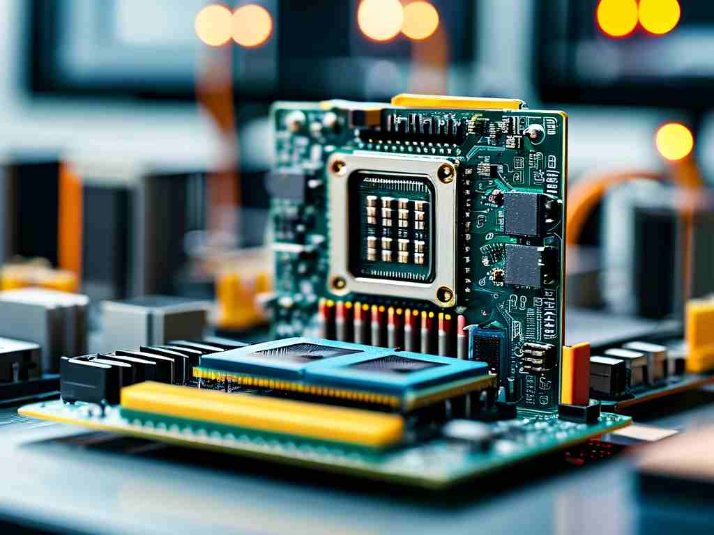
Embedded development testers incorporating dot matrix displays face unique hardware constraints. Unlike standard screens, these matrices require precise control of individual pixels through microcontroller GPIO pins or dedicated drivers. A common approach involves using shift registers like 74HC595 to expand I/O capabilities. For instance, controlling an 8x8 LED matrix typically demands 16 pins – a resource-intensive configuration for compact microcontrollers such as STM32F103 or ESP8266.
Developers often implement multiplexing techniques to optimize pin usage:
void refreshMatrix() {
  for(uint8_t row=0; row<8; row++) {
    digitalWrite(rowPins[row], HIGH);
    shiftOut(dataPin, clockPin, MSBFIRST, buffer[row]);
    digitalWrite(rowPins[row], LOW);
  }
}
This code snippet demonstrates row-by-row refreshing, reducing active pins from 64 to 16 while maintaining display stability through persistence of vision.
Communication Protocol Optimization
Advanced testers employ I2C or SPI interfaces to minimize wiring complexity. Modules like MAX7219 LED drivers convert serial data into parallel outputs, enabling control of 64 LEDs with just three microcontroller pins. Such integration proves invaluable when developing portable diagnostic tools requiring compact form factors.
Software Implementation Strategies
Framebuffer management forms the core of dot matrix software development. Engineers must balance memory allocation with refresh rates – a critical consideration for resource-constrained systems. Bitwise operations become essential for efficient pixel manipulation:
void setPixel(uint8_t x, uint8_t y) {
  displayBuffer[y] |= (1 << (7-x));
}
This function flips individual bits in a byte array representing the matrix state, demonstrating how embedded systems handle graphical data at the register level.
Practical Applications in Testing
-
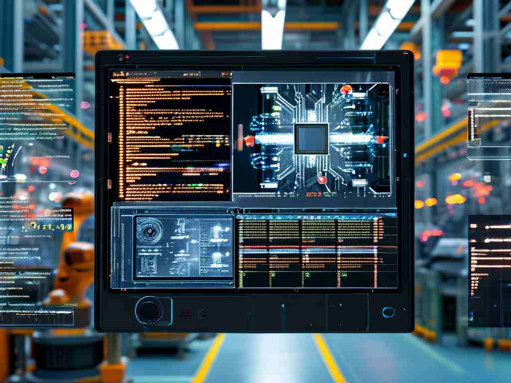
Protocol Visualization
Embedded testers utilize scrolling text displays to monitor UART or CAN bus communications in real-time. A 16x32 RGB matrix can simultaneously display hexadecimal values and error statuses through color coding.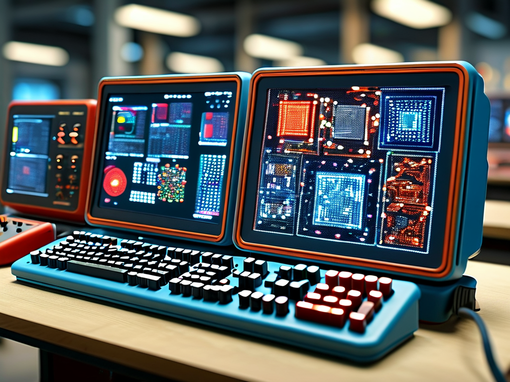
-
Sensor Data Rendering
Environmental testers convert analog sensor readings into dynamic bar graphs. For temperature monitoring systems, a 5x7 matrix might show numerical values alongside trend arrows:void showTemp(int temp) { displayNumber(temp/10); displaySymbol(ARROW_UP); } -
Device Diagnostics
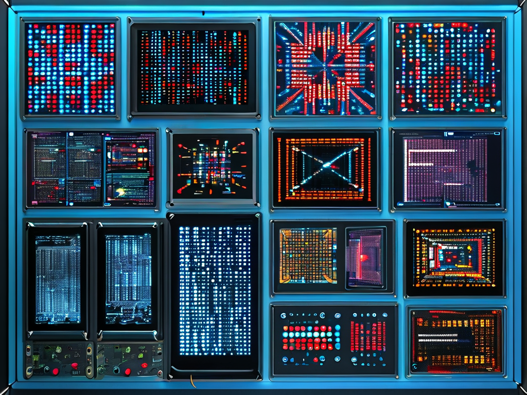
Multicolor dot matrices enable tiered alert systems. Industrial testers might use:
- Red: Critical hardware failures
- Yellow: Communication errors
- Green: Normal operation
Power Management Considerations
LED-based matrices pose significant power challenges. A full-brightness 32x16 red LED display can draw over 500mA – potentially exceeding USB power specifications. Developers implement PWM dimming and sleep modes to address this:
setBrightness(LEVEL_LOW);  // 30% duty cycle
enterSleepMode(5000);      // Auto-sleep after 5s
Future Development Trends
Emerging technologies are reshaping dot matrix applications:
- OLED Integration: Higher resolution self-emissive displays
- Flexible Substrates: Curved surfaces for wearable testers
- AI-Assisted Rendering: On-device pattern recognition for automated fault detection
The evolution of dot matrix technology continues to push boundaries in embedded development. From basic character displays to intelligent diagnostic interfaces, these components remain indispensable for creating intuitive testing environments. As IoT and edge computing advance, expect tighter integration between matrix displays and machine learning frameworks within next-generation embedded testers.