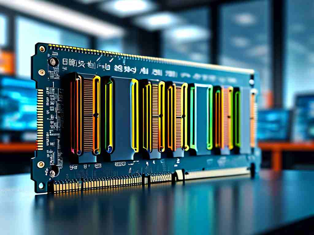
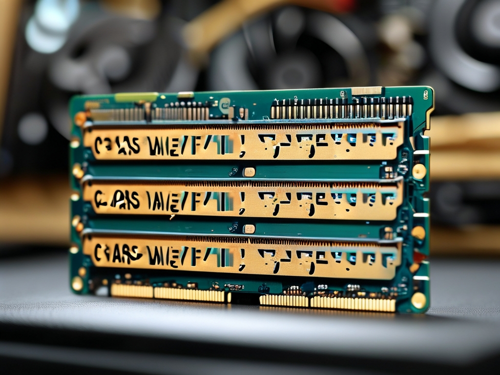
Memory timing segmentation calculation is a critical aspect of optimizing system performance, particularly in high-performance computing, gaming, and data-intensive applications. Memory timings, often referred to as "RAM timings" or "CAS Latency (CL)," determine how quickly a memory module can respond to read/write requests. These timings are represented as a series of numbers (e.g., 16-18-18-36) that correspond to specific latency parameters. Calculating and optimizing these timings requires understanding segmentation methods, which divide the memory access process into discrete phases for precise analysis. Below, we explore the primary methodologies for calculating memory timing segments.
1. Manual Timing Calculation Based on Datasheets
Memory manufacturers provide datasheets that outline default timing values for their modules. Engineers and enthusiasts often use these values as a baseline for manual calculations. Key parameters include:

- CAS Latency (CL): The delay between a read command and data availability.
- tRCD (RAS to CAS Delay): The time required to activate a row and access a column.
- tRP (Row Precharge Time): The delay to close an active row and open a new one.
- tRAS (Active to Precharge Delay): The minimum time a row must remain active.
By analyzing these values, users can manually adjust timings for overclocking or stability testing. For example, reducing CL by one cycle might improve performance but risks instability if the memory cannot handle the faster response.
2. Software-Assisted Timing Segmentation
Tools like Thaiphoon Burner, DRAM Calculator, and BIOS-based utilities automate timing calculations. These programs use algorithms to:
- Profile Memory Chips: Identify the memory module’s manufacturer and IC type.
- Apply Predefined Profiles: Suggest optimized timings based on historical data.
- Simulate Stability: Test hypothetical timing configurations before applying them.
For instance, AMD’s Ryzen DRAM Calculator incorporates memory rank, density, and processor architecture to generate safe overclocking profiles. This method reduces human error but relies on the software’s database accuracy.
3. Mathematical Modeling of Signal Propagation
Advanced calculations involve modeling electrical signal behavior across memory traces. This approach accounts for:
- Trace Length Mismatches: Differences in PCB trace lengths cause signal delays.
- Impedance Variations: Mismatched impedance disrupts signal integrity.
- Clock Skew: Timing discrepancies between memory channels.
Engineers use equations like the Elmore Delay Model to estimate signal propagation times. For example, calculating the tRCD parameter might involve summing the gate delays across the row decoder and column multiplexer. This method is highly precise but requires expertise in circuit design.
4. Machine Learning-Based Timing Optimization
Emerging techniques leverage machine learning (ML) to predict optimal timings. ML models trained on datasets of stable and unstable configurations can:
- Identify Patterns: Correlate timing values with system stability.
- Recommend Adjustments: Propose incremental changes to achieve higher speeds.
- Adapt to Hardware Variations: Account for manufacturing variances in memory chips.
For example, a neural network might analyze thousands of overclocking attempts to predict the safest tRAS value for a specific DDR4 module. While still experimental, this approach promises automated, adaptive optimization.
5. Hybrid Approaches in Industry Applications
In enterprise environments, hybrid methods combine manual, software, and mathematical techniques. Server manufacturers like Dell and HP use proprietary algorithms to balance performance and reliability. These systems often:
- Prioritize Error Correction: Adjust timings to enhance ECC (Error-Correcting Code) efficiency.
- Dynamic Timing Scaling: Adjust timings in real-time based on workload demands.
For example, a data center server might loosen tRP during low-demand periods to reduce power consumption but tighten it during peak loads for faster response.

Challenges in Timing Segmentation
Despite these methods, challenges persist:
- Heat and Voltage Sensitivity: Aggressive timings increase power draw and heat, destabilizing the system.
- Compatibility Issues: Timings optimized for one CPU architecture may fail on another.
- Manufacturer Variability: Even modules with the same label can exhibit timing differences due to silicon lottery.
Memory timing segmentation calculation methods range from manual datasheet analysis to cutting-edge machine learning. Each approach has trade-offs: manual methods offer granular control but require expertise, while software tools simplify the process at the cost of flexibility. As memory technologies like DDR5 and HBM evolve, these methodologies will continue to adapt, driven by demands for faster, more efficient systems. Whether you’re a hobbyist overclocker or a data center engineer, understanding these techniques is essential for unlocking the full potential of modern memory architectures.


